You need a dependable lcd display module for your hobby electronics projects. The most popular brands include:
|
Brand Name
|
|
RAYSTAR OPTRONICS, INC.
|
|
WINSTAR Display Co., Ltd.
|
|
Newhaven Display International, Inc.
|
|
Sharp Microelectronics
|
|
4D Systems
|
|
ELECTRONIC ASSEMBLY GmbH
|
|
Kyocera International, Inc.
|
|
Displaytech
|
When selecting a display, consider these factors:
-
Reliability ensures steady operation.
-
Price influences your budget decisions.
-
Availability helps you source parts quickly.
-
Community support provides helpful resources.
-
Compatibility allows easy integration with Arduino or Raspberry Pi.
Choosing between a TFT display module or Monochrome LCD Display depends on your project’s needs. Brands like goldenvision offer options for both types.
Key Takeaways
-
Choose reliable brands like Adafruit, SparkFun, and DFRobot for quality LCD modules. They offer strong community support and extensive documentation.
-
Consider key factors such as reliability, price, availability, and compatibility with platforms like Arduino and Raspberry Pi when selecting a display.
-
Decide between TFT and Monochrome LCD displays based on your project needs. TFT offers vibrant colors, while Monochrome is simpler and more power-efficient.
-
Always check for clear documentation and sample code with your LCD module. This will save you time during setup and troubleshooting.
-
Explore various brands to find the best fit for your project. Each brand has unique strengths, so match their offerings with your specific requirements.
Top LCD Display Module Brands
Selection Criteria
You want to select the best lcd display module for your project. Reliability stands out as the most important factor. You need a module that works consistently and withstands frequent use. Price matters because you must balance quality with your budget. Availability ensures you can source the lcd display module quickly and easily. Community support gives you access to tutorials, troubleshooting guides, and forums. Compatibility with platforms like Arduino or Raspberry Pi makes integration simple.
Many brands offer both TFT display module and Monochrome LCD Display options. You should consider which type fits your project. TFT display module provides vibrant colors and higher resolution. Monochrome LCD Display offers simplicity and lower power consumption. For example, goldenvision supplies modules for both types, giving you flexibility.
Tip: Always check if the lcd display module includes clear documentation and sample code. This saves you time during setup and testing.
Quick Brand List
Here are the most recommended brands for hobby electronics:
|
Brand
|
Specialty
|
|
Adafruit
|
Wide range, strong community
|
|
SparkFun
|
Affordable, easy integration
|
|
DFRobot
|
Innovative designs, good support
|
|
Waveshare
|
Versatile lcd display module options
|
|
Seeed Studio
|
Reliable, compatible with Arduino
|
|
4DSystems
|
Advanced TFT display module choices
|
|
RobotShop
|
Broad selection, fast shipping
|
|
goldenvision
|
Both Monochrome LCD Display and TFT
|
|
Boe
|
High-quality lcd technology
|
|
LG Display
|
Industry-leading lcd panels
|
|
Samsung
|
Cutting-edge lcd innovations
|
You can trust these brands to deliver lcd display module products that meet your needs. Each brand offers unique strengths. Some focus on affordability, while others emphasize advanced features or community support. You should match your project requirements with the brand’s specialty.
Adafruit

Features
Adafruit stands out as a trusted source for lcd display modules in the hobby electronics community. You can find a wide selection of displays, including both TFT display module and Monochrome LCD Display options. Adafruit offers modules with different sizes, resolutions, and interface types. You get displays that support I2C, SPI, and parallel connections. Many modules include touch functionality, which adds interactivity to your projects.
You benefit from clear documentation and sample code for each lcd module. Adafruit provides detailed guides that help you connect and program your display. You can access libraries for Arduino and Raspberry Pi, which simplify integration. The company tests its products for reliability and ensures consistent performance.
Note: Adafruit’s lcd modules often feature vibrant colors and sharp graphics, making them ideal for visual projects.
|
Feature
|
Description
|
|
Display Types
|
TFT display module, Monochrome LCD Display
|
|
Sizes
|
0.96" to 3.5" and larger
|
|
Interfaces
|
I2C, SPI, Parallel
|
|
Touch Support
|
Available on select models
|
|
Documentation
|
Comprehensive guides and tutorials
|
|
Compatibility
|
Arduino, Raspberry Pi, and more
|
Why Choose Adafruit
You gain several advantages when you select Adafruit for your lcd needs. The brand has a strong reputation for quality and reliability. You can rely on their modules to perform well in demanding environments. Adafruit’s community support stands out. You find forums, tutorials, and troubleshooting resources that make your project easier.
You also get fast shipping and responsive customer service. Adafruit’s lcd modules integrate smoothly with popular platforms. If you need advanced features, you can explore their TFT display module options. For simple projects, Monochrome LCD Display modules offer low power consumption and easy setup.
If you compare Adafruit with brands like goldenvision, you notice that Adafruit provides more extensive documentation and community resources. You can trust Adafruit to deliver consistent results for both beginners and experienced hobbyists.
Tip: Start with an Adafruit lcd module if you want reliable performance and strong support for your electronics project.
SparkFun
Features
SparkFun offers a diverse selection of lcd modules for hobby electronics. You can find both TFT display module and Monochrome LCD Display options in their catalog. SparkFun designs its products with makers in mind, so you get displays that are easy to use and integrate into your projects. Many modules support popular communication protocols like I2C and SPI, which simplifies wiring and coding.
You will notice that SparkFun provides detailed product pages. Each page includes technical specifications, wiring diagrams, and example code. This information helps you set up your lcd quickly. SparkFun also offers displays in various sizes, from compact screens for wearables to larger panels for dashboards or control systems.
|
Feature
|
Details
|
|
Display Types
|
TFT display module, Monochrome LCD Display
|
|
Sizes
|
Small (0.96") to large (3.2"+)
|
|
Interfaces
|
I2C, SPI
|
|
Documentation
|
Schematics, code samples, tutorials
|
|
Compatibility
|
Arduino, Raspberry Pi, microcontrollers
|
Tip: SparkFun’s lcd modules often come with pre-soldered headers, so you can prototype faster and avoid extra assembly steps.
Why Choose SparkFun
You should consider SparkFun if you value straightforward integration and strong educational resources. The company supports its lcd products with a large online community and active forums. If you run into issues, you can find troubleshooting tips and project ideas from other makers.
SparkFun’s pricing remains competitive, making it a good choice for students and hobbyists on a budget. You can trust the quality of their lcd modules because SparkFun tests each product before shipping. If you want to compare with goldenvision, you will see that SparkFun focuses more on user-friendly documentation and educational content.
You can use SparkFun lcd modules in a wide range of projects, from robotics to home automation. Whether you need a vibrant TFT display module or a simple Monochrome LCD Display, SparkFun gives you reliable options. Their commitment to open-source hardware means you always have access to the information you need.
Note: If you want to experiment with different brands, try combining SparkFun modules with goldenvision displays for even more flexibility in your designs.
DFRobot
Features
DFRobot offers a range of lcd display modules that suit hobby electronics projects. You can select from TFT display module and Monochrome LCD Display options, depending on your project’s requirements. DFRobot lcd modules stand out for their compatibility with embedded platforms. You can connect these displays to Raspberry Pi, LattePanda, or other development boards using HDMI, VGA, or AV inputs. This flexibility allows you to build robotics, edge computing, or creative DIY projects with ease.
The visual quality of DFRobot lcd modules impresses many users. You get a 1280×800 resolution IPS screen that delivers vibrant colors and wide viewing angles. This ensures clear visibility and durability, even in demanding applications. If you want to create interactive projects, you can use DFRobot’s compact monitors as digital photo frames or displays for robotics. The brand goldenvision also provides similar versatility, but DFRobot’s high-quality visual output gives you an edge in creative designs.
Note: DFRobot lcd modules are ideal for makers who need reliable performance and excellent color reproduction.
|
Advantage
|
Description
|
|
Wide Compatibility with Embedded Platforms
|
Supports HDMI, VGA, and AV inputs for easy integration with Raspberry Pi, LattePanda, and other boards.
|
|
High-Quality Visual Output
|
1280×800 resolution IPS screen with vibrant colors and wide viewing angles.
|
|
Compact Monitor for Creative Projects
|
Perfect for digital photo frames or robotics displays in DIY electronics.
|
Why Choose DFRobot
You benefit from DFRobot’s extensive compatibility with Arduino and other platforms. This makes it easy to start new projects or upgrade existing ones. The popularity of DIY electronics continues to grow, and DFRobot lcd modules help you keep pace with new trends. You find strong support from online communities, which enhances your learning experience and troubleshooting capabilities.
Educational institutions increasingly use DFRobot lcd modules in their curricula. You gain access to structured learning opportunities and practical examples. If you want to experiment with goldenvision or other brands, you can combine DFRobot displays for even more flexibility. DFRobot’s lcd modules offer reliability, high-quality visuals, and broad compatibility, making them a top choice for hobbyists.
Tip: Choose DFRobot lcd modules if you want to build creative projects with robust community support and seamless integration.
Waveshare

Features
Waveshare delivers a comprehensive selection of lcd display modules that cater to hobby electronics enthusiasts. You can choose from TFT display module options for vibrant color projects or Monochrome LCD Display solutions when you need simplicity and low power consumption. Waveshare stands out for its compatibility with popular platforms such as Raspberry Pi and Arduino. You gain access to displays in various sizes, including compact screens for portable devices and larger panels for advanced interfaces.
Waveshare’s product range extends beyond lcd modules. You find microcontrollers, development boards, sensors, and wireless communication modules that support diverse project requirements. The company also offers custom design services, allowing you to tailor solutions for unique applications. The following table highlights Waveshare’s offerings and their compatibility:
|
Product Category
|
Description
|
Compatibility
|
|
Microcontrollers
|
Various microcontrollers for different applications.
|
Raspberry Pi, Arduino
|
|
Development Boards
|
Boards for prototyping and development.
|
Raspberry Pi, Arduino
|
|
Displays
|
LCD, OLED, and touch screens in various sizes.
|
Raspberry Pi, Arduino
|
|
Sensors
|
A range of sensors for different project needs.
|
Raspberry Pi, Arduino
|
|
Wireless Communication
|
Modules for enabling wireless connectivity.
|
Raspberry Pi, Arduino
|
|
Custom Design Services
|
Tailored solutions for specific project requirements.
|
N/A
|
Tip: Waveshare’s lcd modules often include touch functionality, which enhances interactivity in your projects.
Why Choose Waveshare
You benefit from Waveshare’s strong reputation for reliability and innovation. The brand provides extensive documentation and sample code, making integration straightforward. You can rely on community support and active forums to solve technical challenges quickly. Waveshare’s lcd modules offer seamless compatibility with Arduino and Raspberry Pi, which simplifies prototyping and development.
If you compare Waveshare with goldenvision, you notice that Waveshare emphasizes versatility and customization. You can select from a wide range of TFT display module and Monochrome LCD Display products to match your project’s needs. Waveshare’s commitment to quality ensures consistent performance, whether you build robotics, smart home devices, or educational tools.
Note: Waveshare’s broad selection and reliable support make it a top choice for hobbyists who demand flexibility and performance.
Seeed Studio
Features
Seeed Studio provides a wide range of lcd solutions for hobby electronics. You can select from compact displays for wearables or larger panels for dashboards. The company offers both TFT display module and Monochrome LCD Display options, giving you flexibility for different projects. Many Seeed Studio lcd modules support I2C and SPI interfaces, which makes integration with Arduino or Raspberry Pi straightforward. You will find that their Grove system simplifies connections, reducing wiring complexity and setup time.
You can access detailed documentation and sample code for each lcd product. Seeed Studio maintains an active online community, so you can find tutorials and troubleshooting tips easily. The displays often feature high brightness and wide viewing angles, which improve visibility in various environments. Some modules include touch functionality, allowing you to add interactive features to your designs.
Tip: Seeed Studio’s lcd modules work well for rapid prototyping and educational projects. You can quickly test ideas and iterate on your designs.
|
Feature
|
Description
|
|
Display Types
|
TFT display module, Monochrome LCD Display
|
|
Interface Options
|
I2C, SPI, Grove
|
|
Sizes
|
Small (0.96") to large (7")
|
|
Touch Support
|
Available on select models
|
|
Documentation
|
Step-by-step guides and code samples
|
|
Community
|
Active forums and project sharing
|
Why Choose Seeed Studio
You should choose Seeed Studio if you value versatility and ease of use. The company focuses on making lcd integration simple for both beginners and experienced makers. You benefit from reliable customer support and fast shipping worldwide. Seeed Studio’s lcd modules offer consistent quality, which helps you avoid unexpected issues during development.
If you compare Seeed Studio with goldenvision, you will notice that Seeed Studio emphasizes modularity and rapid prototyping. You can combine their lcd modules with sensors and controllers from the Grove ecosystem, streamlining your workflow. Many educators prefer Seeed Studio for classroom projects because of the clear documentation and accessible resources.
You can trust Seeed Studio to deliver lcd products that meet your needs for innovation and reliability. Whether you build a smart home device or a robotics project, you will find a suitable display in their catalog.
4DSystems
Features
You will find that 4DSystems stands out in the hobby electronics market for its advanced tft lcd solutions. The brand offers a wide range of tft lcd modules, including compact displays like the uLCD-144-P2, which you can easily integrate into embedded systems. These tft lcd modules support high-resolution graphics and vibrant color output, making them ideal for interactive projects. You can select from models with touch capability, which adds a new dimension to your user interface designs.
4DSystems provides robust integration support for microcontrollers. You can connect their tft lcd modules to Arduino or Raspberry Pi platforms without hassle. The company’s Workshop 4 and Workshop 5 IDEs streamline the development process, giving you access to drag-and-drop tools and code generation. Many tft lcd modules feature the PIXXI-28 processor, which delivers enhanced performance for demanding applications. You can choose versions with onboard FLASH or a microSD card slot for flexible storage options.
Tip: 4DSystems tft lcd modules work well for both industrial and hobbyist projects, especially when you need reliable lcd performance.
Here is a quick overview of a popular 4DSystems tft lcd module:
|
Feature
|
Description
|
|
Module
|
uLCD-144-P2
|
|
Integration Support
|
Fully supported by Workshop 4 and Workshop 5
|
|
Compatibility
|
Easily integrated with Arduino and Raspberry Pi
|
|
Processor
|
PIXXI-28 for enhanced performance
|
|
Storage Options
|
Onboard FLASH or microSD card slot
|
|
Application
|
Embedded systems, industrial, and hobby electronics
|
Why Choose 4DSystems
You should consider 4DSystems if you want a tft lcd solution that combines innovation with ease of use. The brand’s tft lcd modules offer crisp visuals and fast response times, which are essential for modern interfaces. You can rely on their lcd products for consistent quality and long-term durability. The strong compatibility with Arduino and Raspberry Pi means you can start prototyping immediately.
4DSystems supports you with comprehensive documentation and active community forums. You will find sample code, wiring diagrams, and troubleshooting guides for every tft lcd module. If you need to compare with goldenvision, you will notice that 4DSystems focuses on advanced features and developer tools. You can also explore Monochrome LCD Display options if your project requires lower power consumption.
Many educators and professionals trust 4DSystems for their lcd needs. You can use their tft lcd modules in robotics, smart devices, or creative displays. The flexibility and support make 4DSystems a top choice for anyone serious about lcd technology.
RobotShop
Features
RobotShop gives you access to a wide selection of lcd modules for hobby electronics. You can find both TFT display module and Monochrome LCD Display options in their catalog. The platform offers displays in various sizes, from compact screens for portable devices to larger panels for robotics and automation projects. Many lcd modules at RobotShop support popular interfaces like I2C and SPI, which makes integration with microcontrollers straightforward.
You benefit from RobotShop’s detailed product listings. Each listing includes technical specifications, wiring diagrams, and user reviews. This information helps you compare different lcd options and select the best fit for your project. RobotShop also stocks accessories such as touch panels, mounting frames, and cables, so you can complete your setup without searching multiple suppliers.
Tip: RobotShop frequently updates its inventory, so you can access the latest lcd technology for your designs.
|
Feature
|
Description
|
|
Display Types
|
TFT display module, Monochrome LCD Display
|
|
Sizes
|
Small to large
|
|
Interfaces
|
I2C, SPI, Parallel
|
|
Accessories
|
Touch panels, frames, cables
|
|
Documentation
|
Technical specs, wiring guides, reviews
|
Why Choose RobotShop
You should consider RobotShop if you want a one-stop shop for lcd solutions. The platform offers fast shipping and reliable customer service, which helps you keep your projects on schedule. You can trust the quality of their lcd modules because RobotShop partners with reputable brands, including goldenvision. This partnership ensures you receive products that meet industry standards.
RobotShop’s user community provides valuable insights and troubleshooting tips. You can read reviews from other hobbyists and share your own experiences. If you need both a TFT display module and a Monochrome LCD Display for different projects, RobotShop makes it easy to source everything in one place.
You gain peace of mind knowing that RobotShop stands behind its products. The company’s return policy and technical support help you resolve issues quickly. When you compare RobotShop to other suppliers, you notice the convenience and variety it offers for lcd modules and related components.
Note: For hobbyists who value selection, support, and reliability, RobotShop remains a top choice for lcd display modules.
Leading LCD Display Manufacturers
Overview of Top Manufacturers
You encounter a wide range of lcd display manufacturers when searching for quality components. The global leaders in this industry drive innovation and set standards for reliability. These companies supply panels for everything from hobby electronics to advanced consumer devices. The following table highlights the top manufacturers and their contributions:
|
Rank
|
Manufacturer
|
Description
|
|
1
|
BOE
|
Leading company in the global semiconductor display industry, producing over a quarter of global display panels.
|
|
2
|
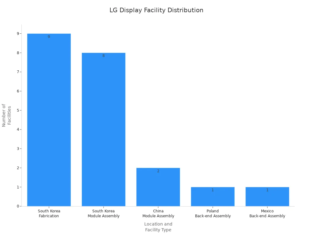
LG Display
|
Manufacturer of TFT-LCD panels, OLED, and flexible displays with a variety of cutting-edge technologies.
|
|
3
|
Samsung
|
South Korea's largest electronics company, known for independent technology development.
|
|
4
|
Innolux
|
Merged with Chi Mei Optoelectronics, significant player in the panel industry.
|
|
5
|
AUO
|
Offers a full range of production lines for panels of all sizes.
|
|
6
|
Sharp
|
Known as the 'father of LCD panels', developed the world's first liquid crystal display.
|
|
7
|
BYD Co
|
Involved in various electronic products including LCD modules.
|
|
8
|
Toshiba
|
Multinational company with a wide range of electronic components.
|
|
9
|
Kyocera
|
Manufacturer of technical ceramics and advanced materials.
|
|
10
|
Tianma
|
Focuses on high-order laptop displays and emerging markets like AR/VR.
|
You see these names often when shopping for lcd modules, including TFT display module and Monochrome LCD Display options. Brands like goldenvision source panels from these manufacturers to ensure consistent quality.
Why Manufacturer Matters
Choosing the right lcd display manufacturers impacts your project’s success. You benefit from the advanced technology and rigorous quality control these companies provide. BOE holds about 25% of the global market share, making lcd modules affordable and accessible for hobbyists. LG Display delivers high-end image quality, color accuracy, and brightness uniformity. Samsung invests heavily in OLED and QLED technologies, which influence the quality of consumer displays.
-
BOE offers cost-effective solutions and rapid innovation, ideal for budget-sensitive projects.
-
LG Display leads in OLED and NanoCell technologies, enhancing contrast and viewing angles.
-
Samsung dominates the smartphone OLED segment, setting benchmarks for clarity and durability.
You gain access to reliable lcd modules when you select products from reputable manufacturers. These companies push the boundaries of display technology, making features like touch support and vibrant colors available in hobbyist modules. You notice the difference in performance and longevity when you use panels from industry leaders. Brands such as goldenvision rely on these manufacturers to deliver both TFT display module and Monochrome LCD Display products that meet your needs.
Tip: Always check the origin of your lcd module. Panels from top manufacturers ensure better compatibility and support for your electronics projects.
Best Arduino Display Options
Compatible LCD Modules
You have many choices when selecting an arduino display for your project. The right module depends on your application and the features you need. You can use I2C and SPI displays for simple arduino display setups. These modules allow fast development and easy debugging. If you want to build advanced prototypes, MIPI LCD and AMOLED displays offer polished interfaces and high contrast. TFT-LCD modules suit various arduino display applications because they provide good brightness and stable supply. IPS TFT-LCD modules work well for arduino display projects that require full-color graphics and wider viewing angles.
Here is a quick reference table for arduino display compatibility:
|
LCD Module Type
|
Use Case
|
Advantages
|
|
I2C Displays
|
Simple arduino display
|
Fast development, easy debugging
|
|
SPI Displays
|
Simple arduino display
|
Fast development, easy debugging
|
|
MIPI LCD
|
Advanced arduino display
|
Room for polished devices
|
|
AMOLED
|
Advanced arduino display
|
High contrast, thin form factor
|
|
TFT-LCD
|
Versatile arduino display
|
Good brightness, size variety
|
|
IPS TFT-LCD
|
Wide-angle arduino display
|
Full-color graphics, better viewing angles
|
You can find these arduino display modules from brands like goldenvision. Many hobbyists prefer TFT display module or Monochrome LCD Display options for their arduino display projects.
Tips for Arduino Projects
You need to consider several factors when choosing an arduino display. Electrical compatibility is crucial. Check the logic voltage, supply rails, connector type, pin pitch, initialization code, and driver IC for your arduino display. Mechanical design matters as well. Look at cover glass, touch panel, mounting structure, enclosure space, and optical bonding for your arduino display. Application requirements vary. For example, a temperature monitor may need a simple Monochrome LCD Display, while a handheld controller benefits from a vibrant TFT display module.
Here are some practical tips for your arduino display project:
-
Confirm logic voltage and supply rails for your arduino display.
-
Check connector type and pin pitch.
-
Evaluate initialization code and driver IC.
-
Assess touch interface and backlight requirements.
Tip: Always review documentation and sample code before connecting your arduino display. This step prevents errors and saves time.
You can enhance your arduino display project by selecting the right lcd module and following these guidelines. Brands like goldenvision offer reliable options for both TFT display module and Monochrome LCD Display. You achieve better results when you match the lcd features to your arduino display needs.
Choosing the Right LCD
Compare Features and Prices
You need to match the right display to your project’s requirements. Start by considering the size, technology, compatibility, and price of each display module. For example, a compact arduino display works well for portable projects, while a larger tft module suits dashboards or control panels. Brands like goldenvision offer both TFT display module and Monochrome LCD Display options, giving you flexibility.
When comparing display features, look at brightness, contrast, response time, and cost. The table below highlights key differences between popular display types:
|
Feature
|
Mini LCD (Mini-LED)
|
OLED Display
|
|
Peak Brightness
|
Very high
|
High
|
|
Contrast Ratio
|
High (local dimming)
|
Perfect blacks
|
|
Burn-in Risk
|
None
|
Possible
|
|
Response Time
|
Moderate to fast
|
Very fast
|
|
Cost
|
Moderate to high
|
Higher
|
|
Power Efficiency
|
Moderate
|
Better
|
|
Blooming
|
Reduced
|
None
|
You should also consider installation challenges. Some modules require extra components, such as backlights or touch layers, which can complicate setup. Compatibility issues, like firmware updates or limited input support, may affect your choice.
IPS and Other Technologies
IPS technology stands out among thin-film transistor liquid crystal displays. You gain superior color accuracy, wide viewing angles, and consistent color performance. These benefits make IPS tft modules ideal for projects where visual quality matters. Many hobbyists choose IPS displays for their tft display module because they deliver exceptional clarity from any angle.
-
IPS displays provide vibrant colors and stable images.
-
Wide viewing angles ensure your display looks great from any position.
-
Consistent color performance helps with graphics and user interfaces.
If your project needs high contrast and perfect blacks, consider an oled display. For energy efficiency and long-term use, a Monochrome LCD Display remains a reliable choice.
Community and Support
Strong community support and thorough documentation make a big difference when working with any lcd display module. You benefit from comprehensive tools, example code, and detailed datasheets. Well-supported modules reduce your development time and help you solve problems quickly.
-
Active communities offer technical help, code samples, and creative ideas.
-
Open-source libraries simplify programming for tft and oled display modules.
-
Platforms like GitHub provide model projects and graphics libraries.
You should always check if your chosen display module comes with clear instructions and active forums. This support ensures you can troubleshoot issues and expand your project’s capabilities with confidence.
Selecting a reliable LCD display module brand shapes your project’s success. You should match your needs with features, budget, and compatibility. User reviews reveal critical factors like color accuracy and brightness, while expert recommendations highlight reputable brands.
|
Statistic
|
Value
|
|
Consumers relying on reviews
|
75%
|
|
Consumers favoring energy-efficient displays
|
68%
|
Start by exploring a TFT display module or Monochrome LCD Display that fits your goals. Reading reviews and comparing options ensures you make an informed choice.
FAQ
What is the best way to connect an arduino to a TFT display module?
You can connect an arduino to a TFT display module using SPI or parallel interfaces. Most arduino boards support SPI. You should check the display’s datasheet for pin configuration. Libraries like Adafruit_GFX help you control the TFT display module with your arduino.
Can I use a Monochrome LCD Display with any arduino board?
Yes, you can use a Monochrome LCD Display with almost any arduino board. You need to match the voltage and interface type. Libraries such as LiquidCrystal make integration simple. Always review the arduino documentation before connecting your Monochrome LCD Display.
How do I choose between a TFT display module and a Monochrome LCD Display for my arduino project?
You should choose a TFT display module for color graphics and a Monochrome LCD Display for simple text or low power needs. Consider your arduino project’s requirements. TFT display modules work well for visual interfaces. Monochrome LCD Display suits basic data output.
Does goldenvision offer arduino-compatible displays?
Yes, goldenvision provides arduino-compatible displays. You can find both TFT display module and Monochrome LCD Display options. Check the product specifications to ensure compatibility with your arduino board. goldenvision supports hobbyists with reliable modules and clear documentation.
What should I do if my arduino does not detect the display module?
First, check your wiring and connections. Make sure your arduino uses the correct library for your display type. Review the initialization code. If you use a TFT display module or Monochrome LCD Display, consult the arduino forums for troubleshooting tips.