Harmonics are extra currents and voltages at integer multiples of the supply frequency that non-linear loads draw on top of the fundamental sine wave. Their effect is costly: transformers, motors and neutral conductors overheat, relays mis-trip, and equipment life shortens even below rated load.
This guide covers measurement at the point of common coupling (PCC) and how to compare the main mitigation technologies.
Why Harmonics Overheat Equipment Below Rated Load
A harmonic current does no useful work: it adds no torque and delivers no real power, only heat. Winding temperature, driven by I²R loss, is the biggest cause of insulation ageing and failure.
Three effects make harmonics more damaging than fundamental current:
- Higher RMS for the same load. A distorted waveform carries more RMS current, so cables and transformers conduct more current than the kW reading suggests.
- Skin and eddy losses. Higher-order current crowds the conductor surface and induces eddy currents in windings, so loss rises faster than at 50/60 Hz.
- Zero-sequence (triplen) current. The 3rd, 9th and 15th harmonics add in phase in a four-wire neutral, so neutral current can exceed phase current.
Relays and breakers respond to RMS or peak, not useful kW, so distortion causes nuisance tripping. Capacitor banks suffer too: their impedance falls as frequency rises and can resonate with system inductance, amplifying one order.
The Physics: Fundamental, Harmonic Order, THD and I²R
The fundamental and individual harmonic orders
The fundamental is the 50 or 60 Hz component delivering real power. A harmonic current sits at an integer multiple of that frequency: on 50 Hz the 5th harmonic is 250 Hz and the 7th is 350 Hz.
THDi, THDv and why one number is not enough
Total Harmonic Distortion (THD) is the RMS value of all harmonic components as a percentage of the fundamental. THDi describes current distortion; THDv describes voltage distortion, which depends on source impedance. A single THDi figure can hide the problem: a filter that cleans the 5th and 7th may leave the 11th and 13th untouched. IEEE 519 and IEC 61000 therefore limit individual orders as well as the total at the PCC.
I²R losses, power factor and reactive power
Harmonic current inflates RMS current, so every extra ampere produces I²R heat. It also distorts power factor: displacement power factor (cos φ) is the phase shift between fundamental voltage and current, while true power factor is real over apparent power (P/S). As distortion grows, true power factor falls even when cos φ looks acceptable, so reactive-power compensation (an SVG) and harmonic mitigation (an AHF) are assessed together.
How Harmonics Damage Your System
Harmonic losses push transformers and motors above design temperature, so they need de-rating and their insulation ages faster; in four-wire distribution, triplen harmonics overload the neutral. Relays, breakers and drives also trip without a real overload, and existing power-factor correction capacitors can resonate with the supply — a recognised fire risk. Table 1 summarises the main sources and the technologies used to control them.
| Harmonic source | Typical orders | Primary system impact | Typical mitigation technology |
|---|---|---|---|
| 6-pulse VFD / rectifier | 5th, 7th, 11th, 13th | Transformer and motor heating; THDi above limits | Active harmonic filter (AHF); line reactor or 12-pulse upgrade |
| 12-pulse rectifier | 11th, 13th, 23rd, 25th | Lower but residual distortion | Passive trap or AHF |
| Single-phase SMPS (PCs, servers, LED drivers) | 3rd, 5th, 7th | Neutral and zero-sequence overload | AHF with zero-sequence capability; de-rated neutral |
| UPS systems | 5th, 7th, 11th | Input THDi; voltage distortion at the PCC | AHF or active front end |
| Arc furnaces / welders | Broadband 2nd–13th plus flicker | Voltage distortion and flicker | SVG combined with AHF; passive filters |
| PV inverters / EV chargers | 5th, 7th plus interharmonics | Voltage distortion and resonance | AHF and SVG |
How to Measure Harmonics at the PCC
Where to place CTs and instruments
Place current transformers (CTs) where responsibility for distortion must be shown — normally at the PCC or on the bus feeding the non-linear loads. For an active filter, the CTs must measure the total load current the filter will correct; CTs on the wrong branch make the filter correct the wrong signal.
What to record
Log THDi and THDv, the individual harmonic orders (at least the 3rd, 5th, 7th, 11th and 13th), neutral current, true power factor and reactive power across a full working cycle. If THDi is rising, our article on what causes high THDi and how to reduce it follows the same diagnostic steps.
| Application | What to measure (and where) | Recommended mitigation | Key selection parameter |
|---|---|---|---|
| VFD-heavy motor plant | THDi and 5th/7th orders at the PCC; duty cycle | Active harmonic filter (AHF) | Filter current rating (A) and CT placement at the load bus |
| Data centre / UPS | Input THDi, bus THDv, neutral current | AHF plus SVG | Neutral and zero-sequence capability; switching frequency |
| Offices, lighting and IT (single-phase) | Triplen (3rd/9th) and neutral current | AHF or de-rated neutral | Zero-sequence current handling |
| Plant with existing capacitor banks | Impedance and resonance scan | Detuned passive filter or SVG | Tuning order and resonance avoidance |
| PV plant / EV charging hub | THDv, flicker and interharmonics at the PCC | SVG with AHF | Response time and dynamic range |
Harmonic Mitigation Technologies Compared
Each technology solves a different part of the problem:
- Passive filter. A tuned inductor–capacitor circuit that diverts a specific harmonic order. Low cost, but fixed: prone to detuning and resonance, so best where the load spectrum is stable.
- Line reactor or active front end (VFD). A reactor adds impedance ahead of a drive; an active front end replaces the diode rectifier. Both cut what one drive injects, but neither corrects other loads.
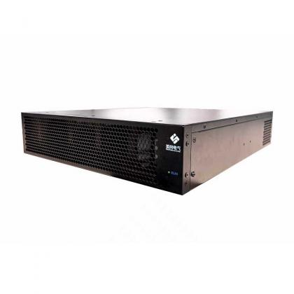
- Active harmonic filter (AHF) / active power filter (APF). Power electronics that measure load current and inject an equal-and-opposite current to cancel harmonics in real time; suited to VFDs, UPS systems and changing loads. The active harmonic filter (AHF) and the active power filter (APF) are examples.
- Static var generator (SVG). A fast reactive-power compensator that holds voltage and power factor steady. The static var generator (SVG) addresses reactive power and voltage stability and is normally paired with harmonic filtering.
How to Select a Harmonic Filter
Size from measurement, not from the transformer rating:
- Filter current. Size the AHF for the harmonic current at the busiest part of the day, with margin for growth.
- CT placement and control. The filter can only correct what its CTs measure; confirm whether the target is the load current, the PCC, or both.
- Topology and switching. A three-level (3-level) topology lowers dv/dt and switching losses versus a two-level design, and a higher IGBT switching frequency widens the range of orders a filter can cancel; confirm these values rather than assume them.
- Environment and de-rating. Ask for the continuous rating at 45°C full load, not a laboratory figure.
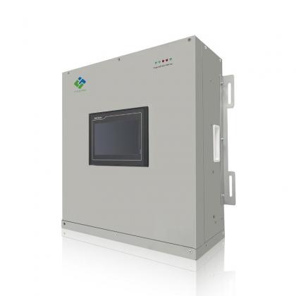
- Redundancy and service. For critical sites, consider parallel modules or wall-mounted units so maintenance does not stop production.
Limitations and When These Solutions Are Not Enough
Filters are effective but not universal, and honest specification means knowing the limits:
- An AHF cancels a limited harmonic current; beyond that, use parallel modules.
- Downstream filters do not remove upstream distortion; verify IEEE 519 at the PCC.
- Passive filters can detune and resonate, so recheck them whenever the network changes.
- An SVG corrects reactive power and voltage, not harmonic current on its own.
- Wrong CT placement makes even a correctly sized filter underperform.
Frequently Asked Questions
How should I measure harmonics before choosing a filter?
Log THDi, THDv, the 5th, 7th, 11th and 13th orders, neutral current and true power factor at the PCC and load bus across a full working cycle. That profile, not the nameplate rating, sets the sizing basis.
Should I choose an AHF, an SVG or a passive filter?
Choose an AHF for harmonic current from VFDs, UPS systems or changing loads; an SVG for reactive power or voltage stability; a passive filter only when the load spectrum is stable and resonance has been checked. Many plants need both.
What is involved in installing a harmonic filter?
Installation is normally a parallel connection on the bus to be corrected, with CTs on the measured load current. The main items are a breaker, cable, enclosure cooling and correct CT polarity; commissioning confirms the cut in THDi and each targeted order.
What maintenance does a filter need, and how is it justified?
Active filters have no moving parts and need only periodic checks of fans, connections and firmware. Justification is rarely a promised payback figure; it is the avoided cost of failures, tripping, downtime and utility penalties, verified against the measured cut in THDi and losses.
Conclusion
Harmonics are a hidden but measurable cost. Once distortion is quantified at the PCC, the right combination of active harmonic filters, static var generators and passive components can cut losses, stop nuisance tripping and extend equipment life. YT Electric (Shanghai Yingtong Electric) manufactures active harmonic filters and static var generators for industrial plants, data centres and renewable-energy projects.
If you would like help measuring harmonics or sizing a filter, get in touch with our team.