Latest Electronics News & Trends | Expert Insights & Innovations

OLED Display Tips to Find Your Perfect Match


Imagine you walk into a store and see many organic light-emitting diode screens. You want the best screen to watch things on, but picking the right portable OLED monitor can be hard. Most people care a lot about how good the screen looks. In fact, 78% of buyers say it is the most important thing when buying devices that cost more than $800. Many people make mistakes like choosing the wrong size, not thinking about the light in the room, or forgetting about how the screen looks from different angles. If you want a display that fits your space and what you need, learning about organic light-emitting diodes and knowing.


Define Your OLED Needs

Main Use Cases

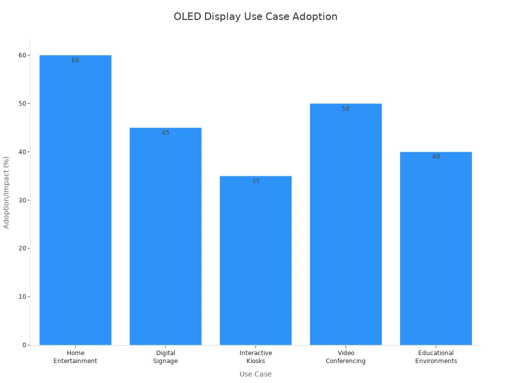
First, think about how you will use your OLED with DC dimming support. People buy these displays for different reasons. Some want to watch movies at home. Others use them for work, playing games, or teaching. The table below shows why people use OLED displays and how popular each use is:

Use Case

Description

Adoption Rate/Impact

Home Entertainment & Personal Use

OLED TVs make movies look better with great colors and contrast.

60% of people who buy expensive TVs pick OLED.

Digital Signage & Commercial Displays

These are good for busy places because the pictures look bright.

OLED signs went up by 45% in two years.

Interactive Kiosks & Public Info Systems

These are used for touch screens in public places.

35% more people use these each year.

Video Conferencing & Corporate Communications

OLED makes online meetings look clear and colorful.

50% more conference rooms use OLED now.

Educational & Training Environments

OLED helps with lessons and showing hard ideas.

OLED use in schools may grow by 40% by 2025.

Bar chart showing adoption rates of OLED displays across five consumer electronics use cases

Space and Environment

Look at your room before you buy a display. Measure the spot where you want to put your OLED display. Check how bright your room is. If your room is very bright, you need a display that is brighter. For public places, pick a display that does not show glare or fingerprints. Think about how many people will watch at the same time. Wide viewing angles help everyone see the screen well.


Feature Priorities

Pick the OLED display features that fit your needs. Most people care about how good the screen looks, but other things are important too. The table below shows what buyers want most:

Feature

Description

Display Quality

People want bright colors, dark blacks, and strong contrast from OLED.

Innovative Form Factors

Some like foldable, curved, or thin screens for style and use.

Sustainability

Many want displays made in ways that are good for the planet.

Durability

People like screens that bend and do not break easily.

Advanced Features

Some want things like fingerprint sensors and fast screen changes.


Decide which features are most important to you. This will help you pick the best OLED display for your life.


Key OLED Display Features

Size and Resolution

Think about the size and resolution before you buy an OLED display. Size means how big the screen is. Resolution tells you how many tiny dots, called pixels, are on the screen. More pixels make pictures look sharper and clearer. If you sit close to your screen, you need a high resolution. This stops you from seeing the little dots. This is important for things like editing photos or watching movies in 4K.


Here is a table that shows some common OLED display sizes and resolutions:

Size (inches)

Resolution (pixels)

Contrast Ratio

Color Gamut Coverage

21.6

3840 x 2160 (4K)

1,000,000:1

80% BT.2020

54.3 x 30.6 cm

1920 x 1080 (Full HD)

N/A

N/A

  • More pixels make images look sharper.

  • How far you sit changes how clear the picture looks.

  • A high PPI screen looks better when you are close.

OLED displays can show true black and many colors. These things make movies, games, and work look great.


Panel Type (WRGB vs RGB)

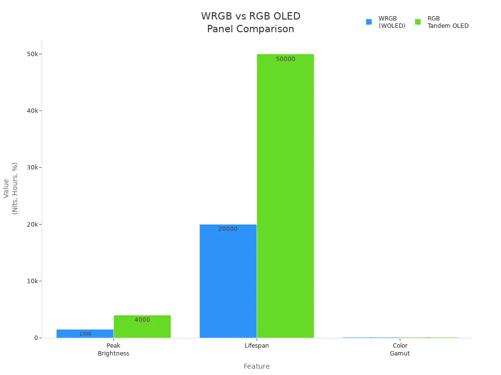
There are two main types of OLED panels: WRGB and RGB OLED. Each type changes how bright, colorful, and long-lasting the screen is.

Feature

WRGB (WOLED)

RGB Tandem OLED

Peak Brightness

1,500 Nits

4,000 Nits

Lifespan

20,000 hours

50,000 hours

Color Gamut

98% (DCI-P3)

99.8% (DCI-P3)

Bar chart comparing peak brightness, lifespan, and color gamut of WRGB and RGB OLED panels

RGB OLED panels are brighter and last longer. They also show colors a little better. WRGB panels are still very good and are used in big TVs. Pick the panel type that fits what you need for brightness and color.


Brightness and Viewing Angles

Brightness is important if your room is bright. OLED displays are usually 800 to 1,000 nits bright. This is good for most homes. QLED displays can be even brighter, up to 2,000 nits. If you want to use your screen in sunlight, you may need a brighter one.

  • OLED screens keep colors and pictures looking good from the side.

  • Each pixel lights up by itself, so colors stay the same.

  • LCD screens can lose color and look worse at sharp angles, but OLEDs do not.

With OLED, everyone in the room sees the same picture, even from the side.


Color Accuracy

Color accuracy means the colors on your screen look real. OLED displays are known for showing colors very well. You can check color accuracy with a number called ΔE00. Lower numbers mean the colors are more correct.

ΔE00

Perception

< 1.0

Not perceptible by human eyes

1–2

Perceptible through close observation

3–10

Perceptible at a glance


If you work with photos or videos, you need a screen with a low ΔE00. This makes sure your colors look right and professional.


Touch Functionality

Touch functionality lets you use your OLED display by touching it. You can tap, swipe, or draw on the screen. This is helpful for designers, teachers, and gamers. It helps you work faster and makes games more fun. OLED screens react quickly, so your touches feel smooth.

Tip: If you want to use your screen for design or games, pick one with touch support.


Connectivity and Compatibility

You need to connect your OLED display to other things. New displays have many ways to connect:

Connectivity Option

Description

Compatible Devices

I2C

Common interface for microcontrollers

Arduino, microcontroller platforms

Qwiic Connectors

Easy cable connection for I2C devices

Arduino, other I2C devices

SPI

Less common, but available on some displays

Some microcontrollers

UART

Serial port connection, rare but possible

Arduino via serial port


Make sure your display works with your computer, game system, or microcontroller. This helps you avoid problems later.


Durability and Build Quality

Durability means your OLED display can handle being used every day. Look for displays that meet rules like ISO 16750 for heat and shaking, or SAE J3168 for seeing the screen in different lights. Some displays also meet car safety rules.

Standard/Certification

Description

ISO 16750

Tests for temperature, humidity, and vibration

SAE J3168

Checks optical performance and readability

ECE Regulation No. 21

Ensures impact resistance and safety

IATF 16949

Quality management for automotive displays


A strong display with good certifications will last longer and work well in many places.


When you know about these features, you can pick an OLED display that fits what you need. You will get great pictures, true colors, and a screen you can trust.


Comparing OLED Models and Brands

 

Reading Specs and Reviews

When you look at OLED displays, start with the specs. Check the size, resolution, brightness, and refresh rate. These things show how the display will work in your room. You should also read reviews from trusted websites. Some good places for reviews and facts are:

  • RTINGS.com: This site has detailed reviews and compares OLED TVs and monitors. You can learn about picture quality and input lag.

  • OLED-Info.com: This site explains OLED technology and gives specs for many displays.

Reading specs and reviews helps you know what to expect before you buy.


Warranty and Support

Warranty and support are important when you buy OLED TVs or monitors. Brands give different warranty times and rules for burn-in. This can change how happy you are with your display. Check the table below to see some choices:

Brand

Model

Warranty Period

Burn-in Policy

ASUS

PG32UCDM

36 months

Covered under warranty

ASUS

Other OLED models

24 months

Not specified

  • Good support helps you fix problems fast.

  • A strong warranty and service are important for business use.

Tip: Always read the warranty rules before you buy. This keeps your money safe if something breaks.


OLED TVs vs Monitors

You should know how OLED TVs and monitors are different. The table below shows how they compare:

Feature

OLED Monitors

OLED TVs

Size

27-32 inches

55 inches and up

Resolution

4K or 1440p

4K is common

Intended Use

Gaming, content creation

General viewing, movies, gaming

Viewing Distance

Close

Farther away

Refresh Rate

Up to 240Hz

Lower refresh rates

OLED monitors show deep blacks and bright colors. They are good for gaming, design, and photos. OLED TVs are better for watching movies in big rooms. Both use OLED technology for great color and contrast, but they are best for different things.


Budget and Value

Balancing Price and Features

You want the best screen for your money. Many people look for high-quality screens, but they also care about price. You should think about what matters most to you. Some people want the newest technology. Others want a screen that lasts a long time. The table below shows what buyers think about when they choose an oled display:

Factor

Description

Display Quality

People want screens that look great and show clear images.

Technological Advancements

New features and improvements attract buyers.

Decreasing Costs

Lower prices make oled displays easier to buy.

Long-term Value

Energy savings and durability help you save money over time.


You can use this table to help you decide what is most important for your needs.


Finding the Best Value

You do not need to buy the most expensive model to get a good oled display. Look for a screen that gives you the features you want at a price you can afford. You can compare different models and brands. Check for things like warranty, support, and extra features. Sometimes, a less expensive model has everything you need.

Tip: Make a list of your top three must-have features. Use this list when you compare displays. This helps you focus on value, not just price.


Timing Your Purchase

You can save money if you buy at the right time. Stores offer big sales during certain months and events. Here are some of the best times to buy an oled display:

  • Black Friday and Cyber Monday: You can find deep discounts on many brands and sizes.

  • Holiday weekends: Stores have special deals and promotions.

  • Amazon Prime Day: Online stores offer exclusive savings.

  • Spring season: Prices drop on older models when new ones come out.

  • Late January to early February: You can find clearance sales after the holidays.

If you wait for these times, you may get a better deal on the oled display you want.


Common OLED Buying Mistakes

Ignoring Compatibility

You might get excited about a new oled, but forget to check if it works well with your devices. Many people run into problems after buying. Some common issues include:

  • Text may look blurry or unclear, especially in Windows.

  • You might see color fringing, which creates colored outlines around letters.

  • Unusual pixel layouts can cause text to look misaligned.

Always check if the oled matches your computer or system before you buy. This step saves you time and frustration later.


Overlooking Durability

You want your oled to last, but not all displays have the same lifespan. QLED and LCD displays often last much longer than oled screens. Burn-in is a real concern for oled users. This happens when images stay on the screen too long and leave marks. QLED technology stands out for its longer life and better durability. Take a look at the table below to see how long each type can last:

Display Type

Lifespan (Hours)

OLED

5,000

LCD

60,000

QLED

Not specified


If you plan to use your display every day, think about how long it will last.


Focusing Only on Specs

You may want the highest numbers, but specs do not tell the whole story. When you focus only on technical details, you can miss important drawbacks:

  1. Oled screens have a shorter lifetime, especially blue oled, which lasts about 1.6 years.

  2. They cost more than LCD displays.

  3. Water can damage them easily.

  4. They do not work as well in bright sunlight.

  5. The screen can get dimmer over time.

  6. Fewer models are available in stores.

Tip: Look beyond the numbers. Think about how you will use your oled and where you will put it.


Skipping After-Sales Support

After-sales support matters more than you might think. Good support helps you fix problems fast and keeps you happy with your purchase. The table below shows why support is important:

Evidence Type

Description

Customer Spending

Customers with great support spend 67% more with a brand.

Customer Loyalty

Fast, helpful support builds trust and keeps you coming back.

Brand Advocacy

Happy customers tell others, which helps the brand grow.


If you skip checking support options, you might regret it later. Always look for brands with strong customer service.


Picking the right OLED monitor for MacBook Pro means you need to think about what is important for your room and what you want. Use this table to help you remember the main things to check:

Key Considerations

Description

Ambient Light Levels

OLED works best in rooms with controlled lighting.

Content Composition

Moving images look best; static images can cause wear.

Viewing Distance

Sit close or mid-range for sharp details.

Panel Handling and Mounting

Handle and mount your display with care for long life.


You should also look at these things before you buy:

  • How good the picture and colors look

  • The design and how it fits your style

  • How much energy it uses

  • If it might get burn-in or how long it lasts

  • The price and if it is worth it

  • How OLED is different from other screens

When you pick a display that fits what you really need, you will not be disappointed. You will enjoy using your screen every day. The best OLED is the one that makes you happy and gives you a great time.
阅读全文......

From Bench to Result Desktop EPR for Real‑Time Spin Analysis

Real-Time EPR Results at the Bench

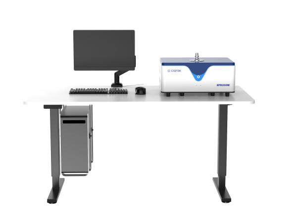
For many U.S. labs, collecting data quickly and efficiently is critical. A desktop EPR brings real-time EPR spin analysis into everyday workflows, allowing scientists to move from sample preparation to results faster. Researchers can monitor dynamic processes such as free radical reactions, material characterization, or biological spin studies with immediate feedback.

Unlike traditional floor-standing EPR systems, a benchtop EPR allows rapid setup and operation without requiring extensive training or dedicated lab space. This makes fast EPR measurement and high-throughput spin analysis accessible for more researchers.


CIQTEK Benchtop EPRModern Benchtop EPR


Why Real-Time Spin Analysis Matters

Many experiments in chemistry, materials science, and biology involve species that change rapidly. Rapid EPR experiments can provide insights that would otherwise take hours or days. With a desktop EPR, researchers can:

  • Acquire spectra quickly with minimal downtime

  • Adjust experimental conditions based on real-time data

  • Iterate experiments more efficiently

  • Reduce sample waste and lab bottlenecks

By enabling real-time EPR measurement, desktop EPR systems support more agile decision-making and accelerate research cycles.


What Makes Desktop EPR Ideal for Modern Labs

Benchtop EPR spectrometers combine a compact design with high performance. Key advantages include:

- Compact EPR Form Factor

A desktop system fits on a standard lab bench, ideal for shared facilities or labs with limited space.

- Intuitive Operation

User-friendly software and controls allow researchers to perform spin analysis without specialized training, supporting multiple users in busy labs.

- Fast EPR Measurement

High-performance detection and streamlined workflows enable rapid spectral acquisition for both solid and liquid samples, making rapid EPR experiments practical.

- Reliable Performance

Modern desktop EPR systems maintain sensitivity and resolution comparable to larger instruments while providing the flexibility of a benchtop unit.

These features make desktop EPR a practical choice for labs that value efficiency and accuracy.


Real U.S. Lab Cases: Faster Workflows and Immediate Feedback in Practice

Real-time EPR is not just a theoretical advantage. In several U.S. research laboratories, desktop EPR systems are already being used to shorten experiment cycles and deliver immediate data feedback, especially in environments where access to large shared instruments is limited or inefficient.


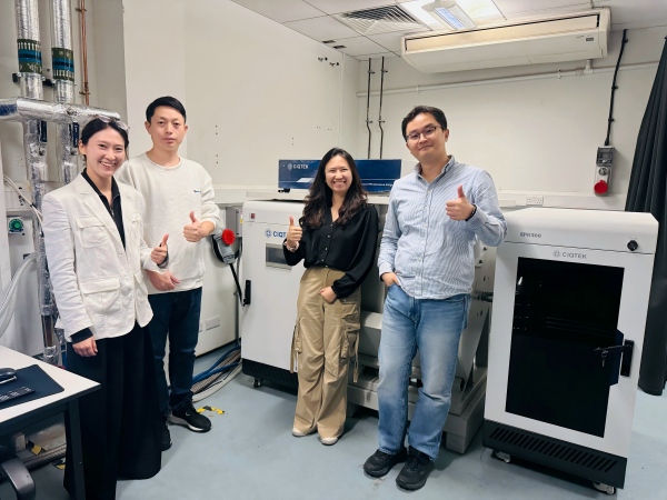
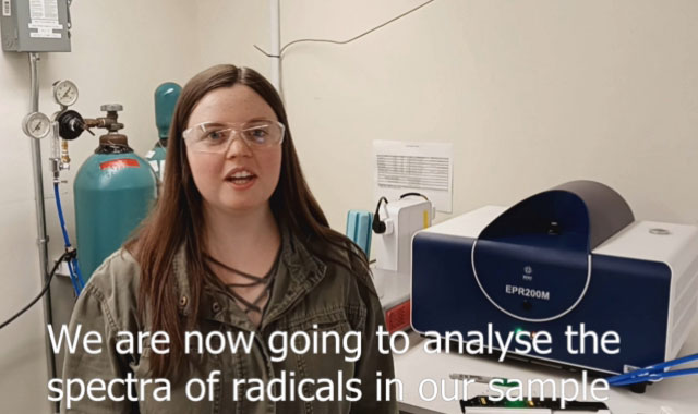
At Cornell University, a CIQTEK benchtop EPR system was introduced to support both biomedical research and teaching. One of the key motivations was workflow efficiency. Instead of scheduling time on a centralized EPR facility, researchers could perform spin analysis directly at the lab bench, immediately after sample preparation. This allowed rapid checks of radical signals and faster decisions on whether experiments should proceed, repeat, or be adjusted. For students and researchers alike, real-time EPR access reduced waiting time and made data interpretation part of the same working session, rather than a separate step days later.


A similar efficiency-driven approach can be seen at Northwestern University, where a CIQTEK desktop EPR200M is used in materials and chemistry research. Researchers value the ability to run fast EPR measurements without interrupting ongoing experiments. Having a benchtop EPR nearby enables quick verification of paramagnetic species during synthesis or material processing, helping teams respond immediately to unexpected results and optimize conditions on the spot.


At the University of Texas at Dallas, the adoption of the CIQTEK desktop EPR system supports both research and instructional use. For teaching labs and student projects, real-time EPR measurements mean that experiments can be completed and discussed within a single lab session. For research users, the system provides rapid feedback during routine spin analysis, improving throughput and reducing dependency on shared, high-demand instrumentation.


Across these U.S. labs, the common theme is not simply access to EPR, but speed and control over the experimental timeline. Desktop EPR systems allow researchers to move from sample to spectrum quickly, integrate data analysis into daily workflows, and maintain momentum in fast-paced research environments.


A screenshot from a user feedback video of the CIQTEK desktop EPR200M from Cornell University.A screenshot from a user feedback video of the CIQTEK desktop EPR200M from Cornell University


How Desktop EPR Boosts Laboratory Productivity

Integrating a benchtop EPR into lab workflows can transform research efficiency. Key benefits include:

  • Shorter setup and measurement times

  • Faster turnaround for real-time EPR experiments

  • Ability to handle higher sample throughput

  • Flexibility for both research and teaching applications

With desktop EPR, labs can achieve rapid EPR experiments and continuous data flow without waiting for traditional instruments.


Performance and Value in One System

A desktop EPR spectrometer delivers strong, high-performance EPR capabilities at a significantly lower cost than many legacy systems. The combination of compact design, quick measurement, and streamlined operation makes benchtop EPR an attractive option for laboratories that need reliable spin analysis without heavy infrastructure or long setup times.

Within this category, CIQTEK desktop EPR systems stand out for their exceptional price-to-performance balance. By focusing on the core measurement needs of modern research labs, CIQTEK offers benchtop EPR instruments that provide robust sensitivity, stable performance, and real-time data access at a price point that is difficult to match. This allows more research groups to adopt EPR spectroscopy as a routine tool rather than a limited shared resource.


For U.S. laboratories conducting spin analysis, CIQTEK benchtop EPR systems deliver immediate results from bench to insight, helping teams maximize research output while keeping capital investment under control. The result is a practical, efficient solution that aligns with both scientific goals and budget realities.

阅读全文......

Upgrading an Aging EPR Spectrometer Extending System Life Without a New Magnet

You Can Extend System Life Without Replacing the Magnet

If your aging EPR spectrometer is 10, 15, or even 20 years old, a full system replacement is often unnecessary.
In many U.S. laboratories, the magnet remains stable and reliable, while performance limitations come from outdated electronics, probes, and software.

By performing a practical EPR spectrometer upgrade, laboratories can restore performance, modernize workflows, and control costs. This approach has already been implemented in real projects and is proving to be both cost-effective and efficient.


Why the Magnet Is Usually Not the Limiting Factor

Magnets are designed for long-term operation and often remain stable for decades with proper care.

In most cases, the magnet provides:

  • Stable magnetic field strength

  • Acceptable field homogeneity

  • Reliable day-to-day operation

The main limitations come from other parts of the system that age faster, such as electronics, control units, and software. This is why many laboratories choose to upgrade their EPR spectrometer without replacing the magnet, focusing on electronics and controls instead of full replacement.


Common Problems with Aging EPR Systems in U.S. Labs

These challenges are common in an aging EPR spectrometer that has been in use for many years.

- Reduced Signal Quality

A lower signal-to-noise ratio makes weak signals harder to detect and increases experiment time.

- Outdated Software and User Interfaces

Legacy software may not run smoothly on modern operating systems and lacks automation features that labs now expect.

- Increasing Maintenance Pressure

Replacement parts are harder to source, and service visits take longer and cost more.

- Limited Support for Modern Experiments

Advanced experiments often require improved timing control, better signal processing, and more flexible system configuration.

These issues typically point to outdated electronics and controls rather than the magnet itself.


What Can Be Upgraded in an EPR Spectrometer

A modern EPR system upgrade focuses on components that limit performance rather than replacing the entire instrument.

- Console and Control Electronics

Upgrading the console improves stability, acquisition speed, and compatibility with modern computers. This is often the most impactful step in the upgrade old EPR spectrometer workflow.

- Microwave Electronics and Detection Chain

Modern microwave electronics reduce noise and improve signal stability, resulting in clearer and more reliable spectra.

- Probes and Resonators

New probe designs can significantly improve sensitivity and ease of use, especially for routine measurements.

- Software and Automation

Updated software simplifies daily workflows, supports automated experiments, and makes the system easier to operate for students and shared facilities.


Upgrade Versus Buying a New System

For many laboratories, upgrading is a practical alternative to full system replacement.

With an EPR system upgrade, labs can:

  • Keep a functioning magnet

  • Reduce capital investment

  • Shorten downtime

  • Minimize disruption to ongoing research

When the magnet remains stable, an EPR upgrade without replacing the magnet often delivers most of the benefits of a new system at a fraction of the cost. This approach is a cost-effective EPR upgrade that many U.S. laboratories are now choosing.


A Real EPR Modernization Case from CIQTEK

A real example comes from Queen Mary University of London, where CIQTEK completed an official EPR spectrometer modernization service.

The laboratory was operating an aging EPR spectrometer that no longer met current research needs. While the magnet was stable, outdated control electronics and system modules limited performance and usability.

Instead of replacing the entire system, the laboratory chose CIQTEK EPR modernization and upgrade service. CIQTEK completed on-site installation, optimized the system, and provided user training.

After the upgrade:

  • System stability improved

  • Daily operation became more efficient

  • The laboratory extended the usable life of its EPR system

  • The high cost and disruption of full replacement were avoided

This demonstrates that upgrading a legacy EPR system is already being implemented successfully in active research environments.


CIQTEK completed the EPR spectrometer modernization service at Queen Mary University of LondonCIQTEK completed the EPR spectrometer modernization service at Queen Mary University of London


Why CIQTEK EPR Upgrades Are Cost-Effective

Budget planning is a critical concern for U.S. laboratories. CIQTEK EPR upgrade service is designed to be cost-effective by focusing on performance-limiting components rather than replacing the entire instrument.

Each upgrade is evaluated based on the existing system's condition, ensuring that resources are used efficiently. This makes the service a truly cost-effective EPR upgrade for labs looking to extend the life of their instruments.


How Long Does an EPR Upgrade Take

Compared with full system replacement, EPR upgrades typically require much less downtime.

  • Hardware preparation is done in advance

  • On-site installation and system validation are efficient

  • User training is included

This allows labs to resume experiments quickly and maintain research continuity.


Moving Forward

If your aging EPR spectrometer still has a reliable magnet but does not meet modern research needs, a cost-effective EPR upgrade is a practical solution.


CIQTEK EPR modernization and upgrade service helps laboratories extend system life, improve performance, and protect research budgets while minimizing disruption. For many U.S. EPR users, upgrading is not a compromise but a smart, strategic decision. 

Learn more about CIQTEK EPR modernization and upgrade service


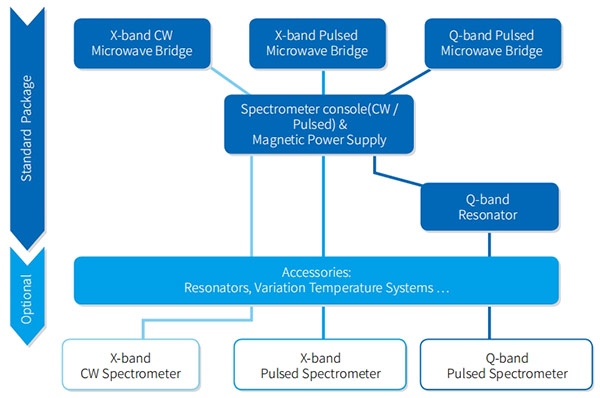
CIQTEK EPR Upgrade WorkflowCIQTEK EPR Upgrade Workflow

阅读全文......

WAIN New Product | M15 Quick-Connect Series Thread-Free Locking for Clear, Simple, and Efficient Installation

To enhance connection efficiency and maintenance convenience for industrial equipment, WAIN officially launches the M15 Quick-Connect Series. This series is designed to address major challenges in on-site installation and long-term maintenance. Its innovative structure is reflected in two core design highlights:


Core Design Highlights

Rapid Locking Mechanism for Higher Installation Efficiency

The connector housing adopts a direct-push quick-connect mechanism. During mating, no manual twisting of the coupling nut is required—simply push to engage, and it locks automatically. This significantly shortens installation time and reduces the difficulty of operating in tight or restricted spaces.

Detachable Contacts for Simplified Maintenance

The contacts use cold-crimp technology and are designed to be separable from the insert. After crimping the cable, the contact can be snapped directly into the side of the contact carrier—quick and intuitive. During maintenance, individual damaged contacts can be replaced without removing the entire connector, offering a more economical and flexible service solution.


Key Features & Advantages


1

Stable Electrical Performance

  Rated  at 63V / 5A, suitable for general industrial applications.

2

Reliable Connection Quality

  Cold-crimped contacts ensure stable, robust performance across diverse industrial environments.

3

Flexible Model Options

  Available in multiple configurations—including assembly-type (panel-mount compatible) and flange   versions (front/rear panel mounting)—to support various installation needs.

4

Multiple Pin-Count Options

  Offered in 9-pin, 12-pin, and 15-pin configurations to meet different signal and power requirements.


Typical Application Scenarios


◆ Industrial automation equipment (e.g., servo motors, robotic arms)
◆ Control systems requiring fast connection and easy maintenance
◆ Modular machine systems


The WAIN M15 Quick-Connect Series delivers a more efficient connectivity solution for both equipment manufacturing and on-site servicing through its optimized structural design.

For more information, please visit the WAIN official website (www.wainelectric.com) or contact us directly.


·END·

WAIN is not only manufacturing, but also creating!

Any questions and ideas related to industrial connectors,

we welcome to discuss with you.

阅读全文......

CIQTEK Named an Official Donor to the University of Strasbourg's Jean-Marie Lehn Foundation

Strengthening Ties with a Leading European University

CIQTEK is pleased to announce its official recognition as a donor to the Jean-Marie Lehn Foundation, part of the University of Strasbourg, France.

As one of Europe's leading research institutions, and ranked No. 1 in the European Union for Chemistry in the 2025 Shanghai Ranking, the University of Strasbourg plays a central role in advancing scientific research and innovation.

The Jean-Marie Lehn Foundation aims to foster collaboration between academia and industry, support scientific research, and nurture young talent. The Foundation promotes innovation, knowledge exchange, and partnerships that advance chemistry, materials science, and related fields.


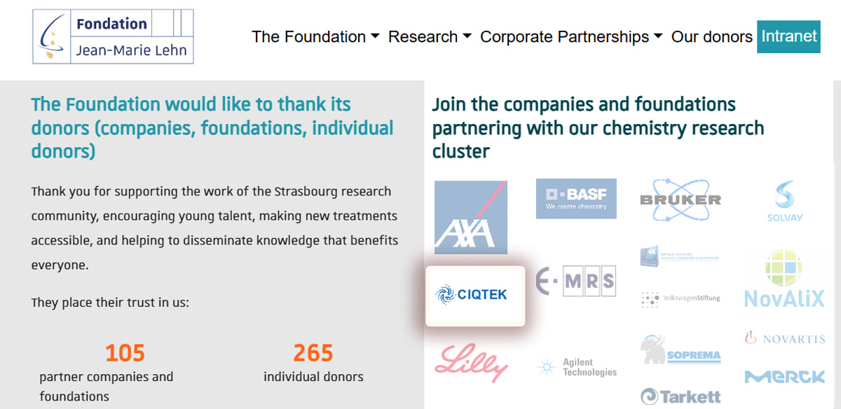
CIQTEK Becomes Official Donor to the University of Strasbourg

CIQTEK logo is now featured on the Foundation's donor page, reflecting the company's commitment to supporting world-class academic development. Source: Jean-Marie Lehn Foundation website


Expanding Collaboration in EPR Research

This milestone also highlights CIQTEK's expanding collaboration with the University of Strasbourg in Electron Paramagnetic Resonance (EPR) spectroscopy. CIQTEK will sponsor the ARPE EPR 10th Summer School, to be held in France from June 22–26, 2026.

During the event, researchers and students will gain hands-on experience with the CIQTEK EPR200M benchtop EPR spectrometer and explore CIQTEK’s advanced floor-stand EPR solutions through real-time remote demonstrations. More details coming soon!


Growing CIQTEK's Presence in France and Europe

Looking ahead, CIQTEK will further strengthen its presence in France and Europe, enhancing brand visibility, expanding collaborations with universities and laboratories, and delivering innovative EPR technologies that accelerate research in materials science, chemistry, and spin-related fields.


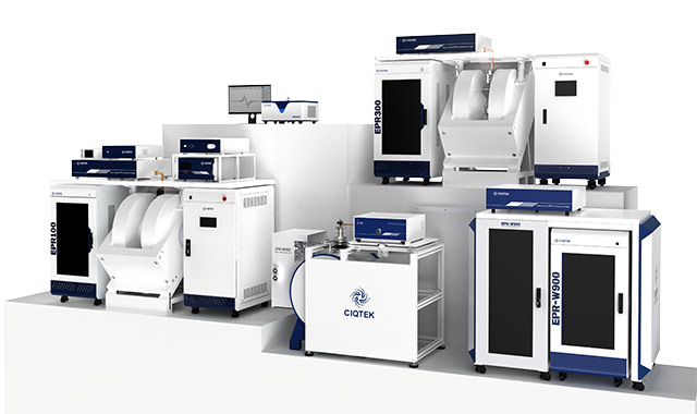
CIQTEK EPR SeriesCIQTEK EPR Spectrometer Series

阅读全文......

Materials and Conductivity Why Terminal Block Quality Matters

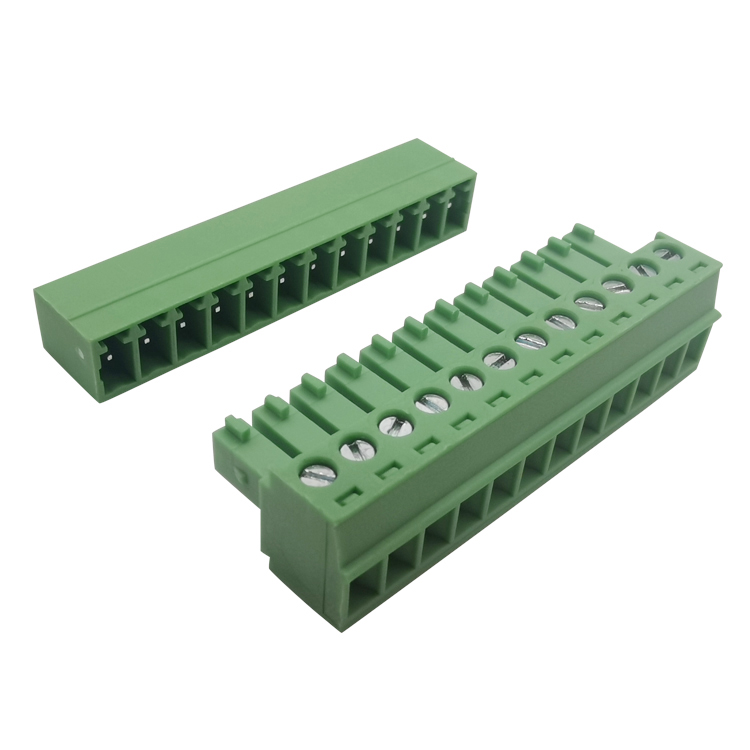
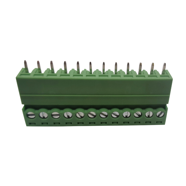
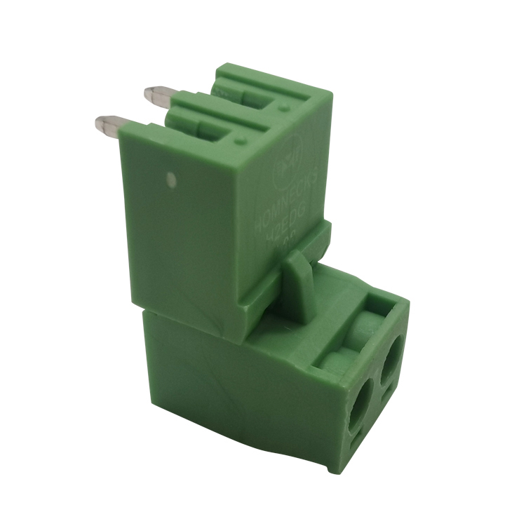
terminal block 12 position

This is an excellent question that directly addresses the core of electrical system reliability. Why terminal block quality so important?because its the key for  integrity, stability, and safety of the "conductive circuit." We can delve into this matter from several dimensions: materials, design, manufacturing process, and practical implications.


1. Materials: The Physical Basis of Conductivity

Conductivity is primarily determined by the material. High-quality terminal blocks are made from materials with excellent conductivity and undergo necessary surface treatments.


Main material (conductive sheet):

Premium Options: High-purity oxygen-free copper (e.g., TU1) or copper alloys (e.g., brass, phosphor bronze). These materials exhibit low resistivity and excellent conductivity, while phosphor bronze also offers superior elasticity and fatigue resistance, ensuring long-term contact pressure maintenance.

Low-quality materials: Using recycled copper with high impurities, copper-clad aluminum, or even iron coated with copper. These materials exhibit high electrical resistance, severe heat generation, and are prone to corrosion, posing significant safety hazards.

Plating layer: Key corrosion-resistant and contact-enhancing layer.

Tinning: The most common method, with moderate cost, effectively prevents copper substrate oxidation while maintaining excellent solderability and contact.

Silver plating: Offers the best conductivity and strong oxidation resistance, commonly used in applications requiring extremely low contact resistance or high-frequency signals (though silver can sulfidize in sulfide environments).

Nickel/Plated Gold: Excellent wear and corrosion resistance, suitable for high reliability, frequent plugging and unplugging, or harsh environments.

Low-quality products: thin and uneven coatings with poor adhesion, which wear or oxidize quickly, leading to a sharp increase in contact resistance.

12 way terminal block

2. Design and Craftsmanship: Transforming Material Properties into Reliable Connections

Good materials require good design and craftsmanship to achieve.


Contact Design:

Pressure and Area: The spring or screw structure must provide sufficient, stable, and uniform contact pressure. Insufficient pressure results in high contact resistance, while excessive pressure may cause plastic deformation of the cable or spring, leading to failure.

Contact point protection: The design should minimize the erosion of contact points by environmental factors (dust, moisture, corrosive gases).


Structural Strength and Insulating Materials:

Insulated housing: Must be made of flame-retardant, high-temperature-resistant, and high-CTI (Comparative Tracking Index) engineering plastic (e.g., PA66+GF). Inferior plastics are prone to aging, deformation, or even combustion, which can cause short circuits or fires.


Mechanical strength: Structures such as clips, guide rail grooves, and screw mounting seats must be robust and capable of withstanding stresses from installation, operation, and vibration.


Process consistency:

Precision Machining: Ensure consistent dimensions and tight tolerances at every contact point.

Reliable fasteners: The strength of screws, thread accuracy, and anti-loosening designs (such as screws with saddle washers) are crucial.


Conclusion: Terminal blocks are the "gatekeepers" of system safety

In modern electrical and control systems, although terminal blocks are inconspicuous passive components, they undertake multiple key functions such as current transmission, signal connection, circuit isolation, and physical fixation.

High quality terminal block: Like a loyal "goalkeeper", it ensures low loss, zero distortion, and high reliability of electrical energy and signals, resists environmental erosion and mechanical stress throughout the entire life cycle of the equipment, and is the cornerstone of safe, stable, and efficient system operation.


Low quality terminal block: It is a hidden time bomb in the system. The small cost savings it saves are completely insignificant compared to the potential costs of equipment damage, production downtime, data loss, and even personal safety accidents.

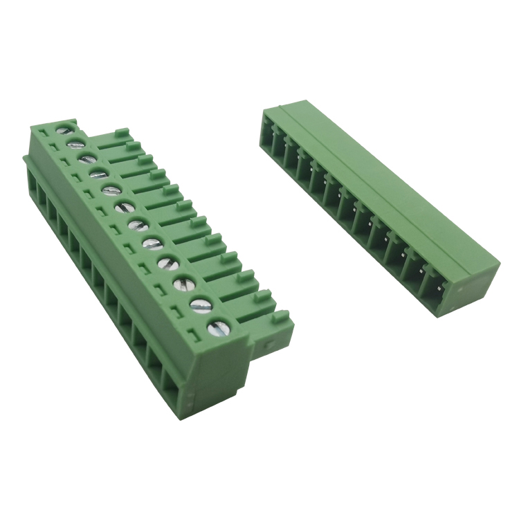
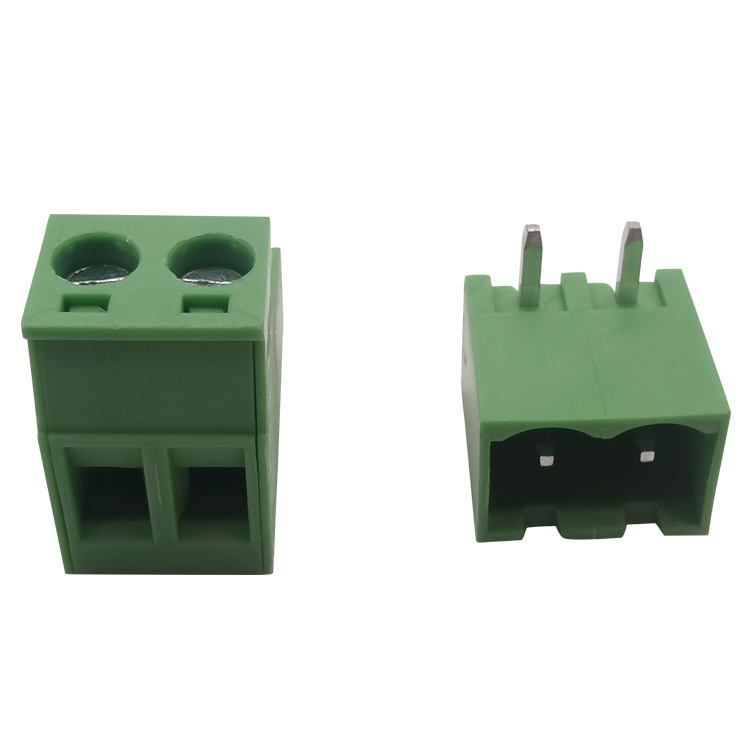
3.5 mm screw terminal block


Therefore, when choosing a terminal block, it must not be regarded as a simple "wiring tool". The strict requirements for its materials (conductivity and coating), design (contact and insulation), and process (consistency) are the basic guarantees for the investment and personal safety of the entire electrical system. Always adhere to selecting products that comply with international standards (such as UL, IEC, VDE) and come from reliable manufacturers, which is the wisest choice.

阅读全文......

Corrosion Science Spotlight CIQTEK SEM in Steam Oxide Film Analysis

Nuclear fusion is considered a key future energy source due to its high efficiency and clean energy output. In fusion reactors, water cooling systems are widely used because they are technically mature, cost-effective, and have excellent cooling performance.

However, a major challenge remains: under high temperature and high pressure, water and steam strongly corrode structural materials. While this problem has been studied in fission reactors, fusion environments are more complex. The unique high-intensity, unevenly distributed magnetic fields in fusion devices interact with corrosion processes, creating new technical challenges that need detailed research.

To address this, Associate Professor Peng Lei's team from the University of Science and Technology of China conducted an in-depth study using the CIQTEK scanning electron microscope (SEM) and dual-beam electron microscope. They built high-temperature magnetic-field steam corrosion and high-temperature water corrosion setups. Using SEM, EBSD, and FIB techniques, they analyzed oxide films formed on CLF-1 steel after 0–300 hours of steam corrosion at 400°C under 0T, 0.28T, and 0.46T magnetic fields, and after 1000 hours of high-temperature water corrosion at 300°C.


The study used CIQTEK SEM5000X ultra-high-resolution field-emission SEM and the FIB-SEM DB500The study used CIQTEK SEM5000X ultra-high-resolution field-emission SEM and the FIB-SEM DB500


The study found that the oxide films form a multilayer structure, with a chromium-rich inner layer and an iron-rich outer layer. Film formation occurs in five stages: initial oxide particles, then floc-like structures, formation of a dense layer, growth of spinel structures on the dense layer, and finally, spinel cracking into laminated oxides. The presence of a magnetic field significantly accelerates corrosion, promotes the transformation of outer magnetite (Fe₃O₄) into hematite (Fe₂O₃), and enhances laminated oxide formation. This work was published in Corrosion Science, a top-tier journal in the field of corrosion and materials degradation, under the title: "Magnetic field effects on the high-temperature steam corrosion behavior of reduced activation ferritic/martensitic steel."


Magnetic field effects on the high-temperature steam corrosion behavior of reduced activation ferritic/martensitic steel.


Surface Oxide Film Characterization

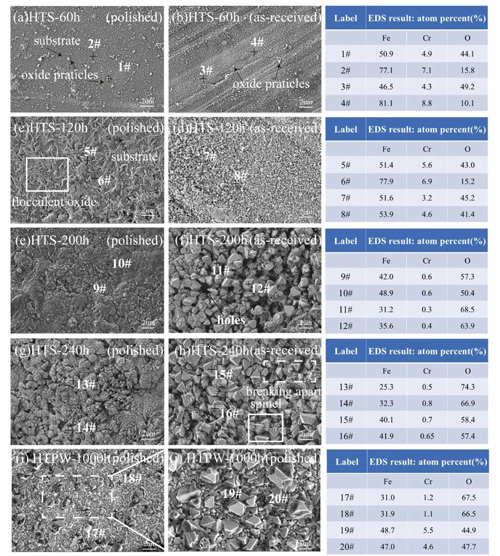
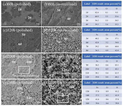
In high-temperature steam (HTS), CLF-1 steel surfaces show different corrosion states over time. On polished surfaces, early-stage oxidation (60 h) appears as small, dispersed particles. The Fe/Cr ratio is similar to the substrate, indicating that the oxide layer is not yet complete. By 120 h, floc-like oxides appear. At 200 h, a dense oxide layer forms, with new oxide particles and local spinel structures on top.

Rough surfaces corrode faster. Early floc-like oxides are finer and more evenly distributed. By 200 h, they transform into spinel structures, showing a stronger difference from polished surfaces. In high-temperature, high-pressure water (HTPW), polished surfaces display similar spinel structures. Spinel in HTPW is denser and more numerous, while spinel in HTS is larger in size.

When a magnetic field is applied (0.28 T on polished, 0.46 T on rough), corrosion changes further. After 60 h, oxide particles appear on both surfaces, more on rough surfaces. By 120 h, polished surfaces have particle-like oxides, while rough surfaces develop fine floc-like films. At 200 h, rough surfaces show spinel cracking and layered structures perpendicular to the surface, with many pores forming. By 240 h, layers become denser and well-aligned. EDS analysis shows that under magnetic fields, Fe/Cr decreases and oxygen increases over time. Cr content drops at 120 h, earlier than in non-magnetic conditions, showing that magnetic fields accelerate the formation of the iron-rich outer layer.


Figure 1. SEM images and EDS point scans (#1–#20) of CLF-1 surfaces under HTS and HTPW.Figure 1. SEM images and EDS point scans (#1–#20) of CLF-1 surfaces under HTS and HTPW.


Figure 2. SEM images and EDS point scans (#1–#16) of CLF-1 surfaces exposed to magnetic fields: polished (0.28 T), rough (0.46 T).Figure 2. SEM images and EDS point scans (#1–#16) of CLF-1 surfaces exposed to magnetic fields: polished (0.28 T), rough (0.46 T).


Oxide Film Phase Analysis

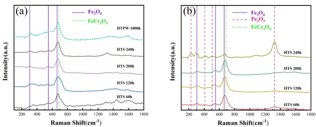
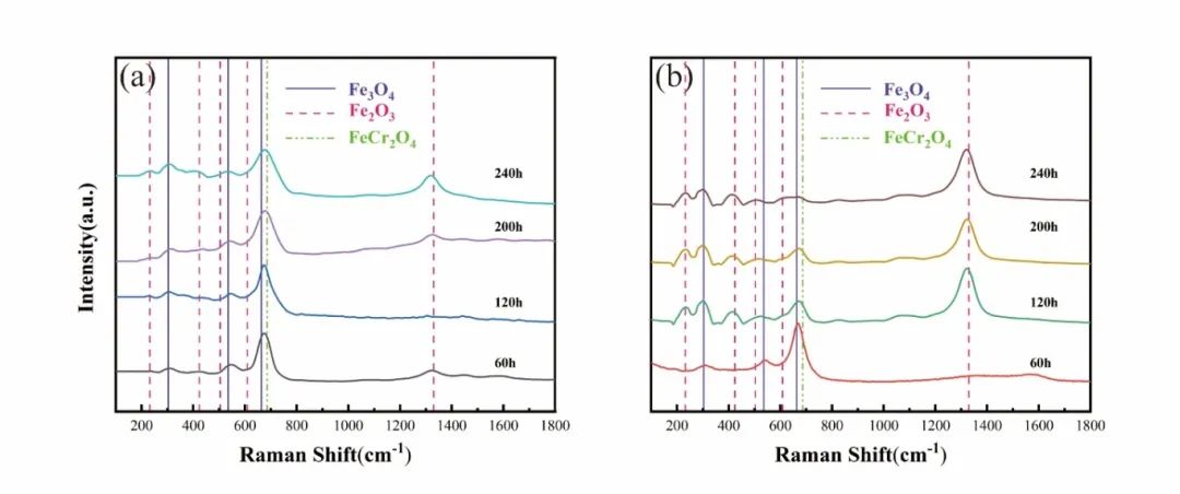
Figures 3 and 4 show Raman spectra of CLF-1 steel oxide films in HTS, HTPW, and under magnetic fields. Without a magnetic field, films in both HTS and HTPW are mainly spinel structures composed of Fe₃O₄ and FeCr₂O₄. The Raman peaks (302, 534, 663, 685 cm⁻¹) overlap, making differentiation difficult. Hematite (Fe₂O₃) appears only on rough HTS surfaces after 240 h.

Under a magnetic field, oxidation accelerates. Polished surfaces show small Fe₂O₃ peaks only at 240 h, while rough surfaces show Fe₂O₃ as early as 120 h, increasing by 240 h. Meanwhile, Fe₃O₄ and FeCr₂O₄ peaks weaken, indicating faster hematite formation.


Figure 3. Raman spectra of oxide films on CLF-1 under HTS and HTPW: (a) polished; (b) rough.Figure 3. Raman spectra of oxide films on CLF-1 under HTS and HTPW: (a) polished; (b) rough.


Figure 4. Raman spectra under magnetic field HTS: (a) polished (0.28 T); (b) rough (0.46 T).Figure 4. Raman spectra under magnetic field HTS: (a) polished (0.28 T); (b) rough (0.46 T).


Cross-Section Oxide Film Characterization

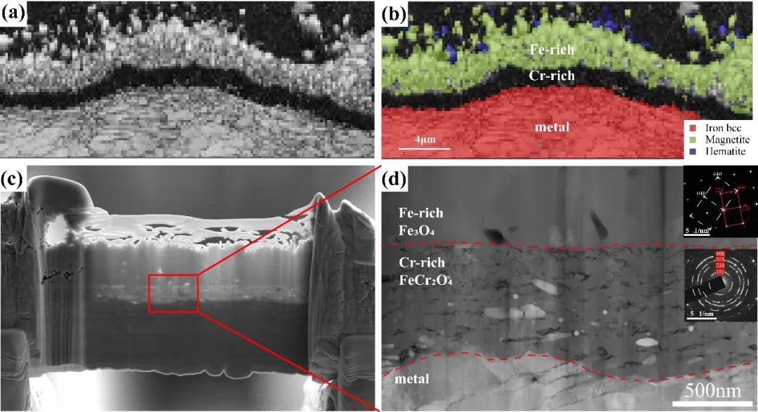
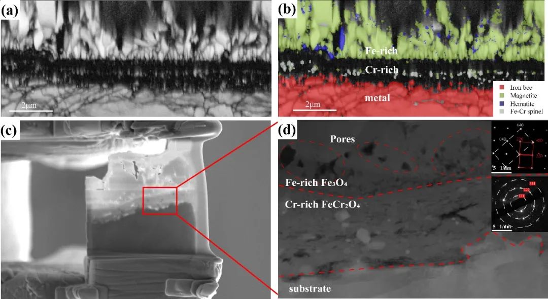
EBSD analysis of rough surfaces after 300 h HTS corrosion (Figure 5a, b) shows a three-layer oxide structure: a thin, discontinuous Fe₂O₃ outer layer, a dense Fe₃O₄ middle layer, and a black chromium-rich layer between Fe₃O₄ and the substrate. FIB-prepared cross-sections (Figure 5c, d) and TEM/SAED analysis confirm that the chromium-rich layer is FeCr₂O₄, and the iron-rich layer is Fe₃O₄. Gaps at the interfaces indicate phase separation and pore formation during oxidation evolution.


Figure 5. Microstructure and phase distribution of cross-section oxide films on rough CLF-1 surfaces after 300 h HTS: (a) EBSD contrast; (b) EBSD phase map; (c) FIB cross-section; (d) dark-field TEM and SAED.Figure 5. Microstructure and phase distribution of cross-section oxide films on rough CLF-1 surfaces after 300 h HTS: (a) EBSD contrast; (b) EBSD phase map; (c) FIB cross-section; (d) dark-field TEM and SAED.


Figure 6 shows cross-sections under a magnetic field (HTS, 240 h). EBSD shows outer oxides composed of Fe₃O₄ and Fe₂O₃. Fe₃O₄ layers are vertically aligned with many pores, and Fe₂O₃ fills surface gaps. The chromium-rich layer between the outer layer and substrate is porous. Compared with non-magnetic conditions, films are looser with more pores, especially at layer interfaces and within the Fe-rich layer. SAED confirms that oxide films still consist of FeCr₂O₄ and Fe₃O₄ from inner to outer layers. Magnetic fields mainly affect film density and pore evolution, not phase composition.


Figure 6. Cross-section microstructure and phase distribution of rough CLF-1 surfaces under magnetic field HTS: (a) EBSD contrast; (b) EBSD phase map; (c) FIB cross-section; (d) dark-field TEM and SAED.Figure 6. Cross-section microstructure and phase distribution of rough CLF-1 surfaces under magnetic field HTS: (a) EBSD contrast; (b) EBSD phase map; (c) FIB cross-section; (d) dark-field TEM and SAED.


This study examines the effect of magnetic fields on CLF-1 steel corrosion after 300 h in 400°C HTS. It also compares oxide films formed under HTPW and HTS conditions. The findings provide important reference data for optimizing the corrosion resistance of fusion structural materials.

阅读全文......

The Working Principle and Design Structure of Terminal Blocks

Terminal blocks are one of the most basic and crucial components in electrical connections, with the core objective of achieving safe, reliable, and convenient wire connections.

8 pole terminal  block

I. Operating Principle

The basic principle of a 8 pole terminal  block can be summarized as follows: through a mechanical structure and a conductor, it establishes a low-resistance, high-stability electrical path between conductors (such as wires), while ensuring a firm mechanical connection and preventing accidental contact.


This principle primarily relies on the following key points:

Electrical conduction: The core conductor of the terminal (usually copper or copper alloy) provides the main path for current flow. Its excellent conductivity ensures low energy consumption and low heat generation.

Mechanical clamping: Through screws, springs, or other mechanical devices, a substantial contact pressure (clamping force) is exerted on the inserted wire. This force serves two important purposes:

Destruction of oxide layer: The oxide film on the surface of the wire is non-conductive. A strong clamping force can crush this thin film, enabling true contact between metals.

Maintain contact: Prevent wire loosening caused by vibration, thermal expansion and contraction, or external force pulling, and maintain stable contact resistance.


Minimizing Contact Resistance: Ideally, the flow of current from a wire to a terminal and then to the next conductor should be as smooth as possible. Good design and clamping force can ensure that the resistance at the contact point is much lower than the resistance of the wire itself, thus preventing the point from becoming a "hot spot".

Durable H28S-7.62 Barrier Block

II. Design Structure

Despite the diverse shapes of wiring terminals, most of them consist of three basic components:

1. Conductive material: Typically, metals with high conductivity are used, such as brass, phosphor bronze, and copper alloys. Sometimes, they are plated with tin, nickel, or silver to enhance corrosion resistance, reduce contact resistance, and improve solderability.

Function: This is the core channel for current transmission. It is designed to connect reliably with wires and form an electrical interface with matching terminals or devices.


2. Insulating shell material for 8 position terminal block : Engineering plastics, such as polyamide (PA66, nylon), polycarbonate (PC), PET, etc., are commonly used. These materials exhibit good electrical insulation, mechanical strength, flame retardancy (such as UL94 V-0 grade), and heat resistance.


3. Clamping mechanism is the key part to distinguish different types of terminals. There are mainly the following mainstream designs:

a) Screw connection type

Structure: By rotating the screw, a metal pressure plate or conical nut is driven to directly compress the wire.


Advantages:

The connection is firm, with a large contact area and strong current-carrying capacity.

Suitable for connecting single-strand (solid) wires and multi-strand wires with wire lugs.

Disadvantages:

It may loosen in a vibrating environment, so regular inspection and tightening are required.

The connection speed is relatively slow.

For multiple thin wires, if a wire nose is not used, some copper wires may be crushed and broken during tightening.

b) Spring connection type (cage spring/compression spring type)

Structure: Utilize a pre-tensioned V-shaped or other shaped spring leaf. Insert a straight screwdriver into the operating hole to open the spring. After inserting the wire, withdraw the screwdriver, and the spring will rebound, firmly pressing the wire against the internal conductive strip.


Advantages:

Vibration resistance: The continuous pressure of the spring can compensate for the looseness caused by thermal expansion and contraction and vibration, making it very reliable.

Quick wiring: No need to twist screws, greatly improving wiring efficiency.

Suitable for multi-strand wires and thin wires with casings.

Disadvantages:

Strong dependence on tools (requires a screwdriver of a specific size).

The current-carrying capacity is generally slightly lower than that of screw connections of the same size (but it is sufficient in most cases).

c) Direct plug-in connection

Structure: This is a simplified form of spring connection. It usually has a small hole, into which a stripped and untreated solid wire is directly inserted with force. The internal spring mechanism will automatically clamp the wire. To release the wire, you need to press the release button next to it.


Advantages:

It is extremely fast and convenient, and the terminal block 10 pin can be made without any tools.

Disadvantages:

It is usually only applicable to solid conductors.

The current-carrying capacity and wire diameter range are limited.

d) Insulation displacement connection

Structure: Inside the terminal, there are sharp V-shaped metal contacts. When a unstripped wire is pressed firmly into the designated position, the sharp contacts pierce through the insulation and make direct contact with the internal metal conductor.


Advantages:

No need to strip the wire, saving time and effort, and avoiding problems caused by improper wire stripping length.

The connection is fast and reliable.

Disadvantages:

There are strict requirements for the specifications of the wires and the thickness of the insulation.

It is commonly used in signal current applications such as communication, data networks (such as RJ45 connectors), and home appliances.

PCB terminal block

III. Main Types and Applications

According to application scenarios, terminal blocks mainly come in the following forms:

PCB terminal block: soldered onto a printed circuit board, used to connect external wires to the circuit board.

DIN-rail terminal blocks: They can be clipped onto standard DIN rails and are widely used in industrial control cabinets and distribution boards, facilitating modular installation and maintenance.

Barrier terminal block: 12 position terminal block Equipped with plastic partitions, it is commonly used in high-voltage and high-current applications such as power distribution, effectively preventing short circuits between different polarities.

Socket terminal: used for connecting devices that require frequent plugging and unplugging.


IV. Design Considerations and Selection Key Points When designing or selecting terminal blocks, the following factors must be considered:

Current and voltage ratings: These are the most crucial parameters, which must meet or even exceed the maximum demand of the circuit, while leaving a margin.

Wire type and specification: Is it a single-strand wire or a multi-strand wire? What is the wire diameter (AWG or square millimeter)? This determines which clamping mechanism should be selected.

Environmental conditions: Is it exposed to high vibration, high temperature, high humidity, or corrosive environments? This affects the selection of materials (such as housing plastics, plating layers) and connection methods (such as spring connections for better vibration resistance).

Safety certification: Whether it is necessary to comply with safety standards in specific regions, such as UL (United States), UL (Canada), CE (Europe), VDE (Germany), etc.


Number of wires and spacing: How many wires need to be connected? Does the spacing (pitch) between terminals meet the requirements for electrical clearance and creepage distance?


Summary

Although terminal blocks are small components, they are the "joints" of the electrical system. Their working principle is based on reliable mechanical clamping to achieve low-resistance electrical contact. Their design structure revolves around three major elements: conductors, insulating shells, and clamping mechanisms. For different application needs, various clamping technologies such as screws, springs, direct insertion, and insulation displacement have been derived. Proper selection and installation are the foundation for ensuring long-term stability and safe operation of the entire electrical system.


阅读全文......

WAIN Vehicle-Mounted | New Energy High-Voltage PDU Connectors

As the electrification of commercial vehicles and construction machinery accelerates, WAIN delivers a cutting-edge solution: our integrated metal-shell connectors designed specifically for high-voltage power distribution units (PDUs). Engineered for demanding environments, this series combines robust performance with installation efficiency.

Exceptional Load Capacity – Precision-engineered design supporting 1–4 core configurations, with a maximum voltage rating of 2000 V and current up to 450 A.

Comprehensive Protection – Certified IP67/IP6K9K sealing with 360° shielding to safeguard against harsh environmental conditions and electromagnetic interference.

Versatile Installation – Multiple keying options and straight or angled cable outlets ensure optimal compatibility and significantly reduce installation time.

Proven in the field, these connectors are already in bulk supply to multiple Tier 2 high-voltage component manufacturers, delivering stable performance and reliable integration. Today, they are enabling mass-production applications across a wide range of commercial vehicles and construction machinery, helping power the next generation of new energy transportation. 

阅读全文......

High-Efficiency, Globally Compliant Wall-Mount Power Adapter

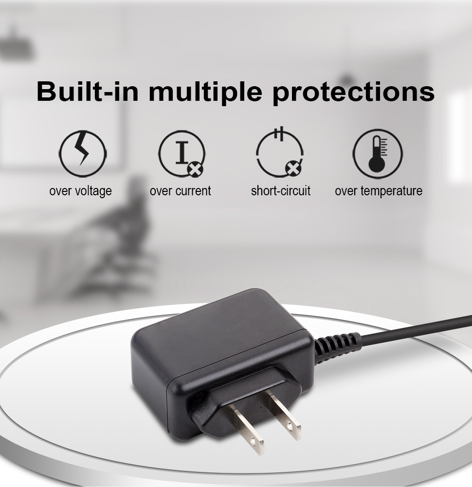
Stable output and space efficiency are equally important. This wall-mount power adapter delivers a 5W, 12W, 36W, 65W or 100W efficient output with a compact chassis and excellent thermal management, ensuring stable power even with load fluctuations. The global design provides regional plug variants for US/AU/UK/EU, helping enterprises deploy quickly and compliantly in global markets.

12W Wall-type Power Adapter

To boost reliability, it features multiple protections: overvoltage/overcurrent/short-circuit/overtemperature/undervoltage protection, plus built-in self-check and power-off protection. It can self-diagnose and safely shut down in abnormal conditions, reducing the risk of equipment damage. A unified performance specification and certification framework make cross-region deployment more efficient, lowering certification and implementation costs.

This wall power adapter is ideal for demanding setups such as CCTV power supply and alarm systems power supply, delivering stable performance for cameras, sensors, and access control devices. With a focus on compact form factor, ease of installation, and robust protection features, it ensures continuous, trouble-free operation in security and monitoring environments.

阅读全文......